ModSystem

Voxa Harmonia · ModSystem

MIDI electronics for your organ.

Building an organ console, converting an existing manual or looking for electronics for your stop controls? ModSystem brings together controller and connection boards designed for specific tasks. Explore the options for key sensing, stop inputs, expression pedals and LED feedback, then visit Voxa Harmonia to discuss the modules your project needs.

Organ electronicsMIDI controlModular design
MODSYSTEM / CONTROL01 — 10
Control Modul Driver — PCB illustration
Central controller · PCB illustrationControl Modul Driver

Inputs matched to the sensors

Digital Hall switches, reed contacts and analogue Hall sensors produce different signals. Choosing a manual board starts with the keyboard mechanism and the function you need. This makes sensor requirements and wiring arrangements explicit before the console electronics are assembled.

Feedback with its own design choices

Reading a stop switch and driving its indicator are related tasks with different electrical requirements. The range includes an integrated stop and LED board as well as a separate USB-MIDI LED controller. Select the approach according to the layout, channel count and feedback behaviour required.

A clear system plan

The central controller, input boards and matrix connection boards have distinct roles. Document the manuals, pedalboard, stop banks and power supplies in one plan. That provides a useful basis for selecting components, checking connections and discussing a project quotation.

01 / MODSYSTEM

Modules from key sensing to visual feedback

Ten modules cover central control, key sensing, stop inputs and matrix connections. Compare their technical descriptions to identify the functions your project needs. Manual 64 Velocity is a variant still in development.

10 / 10 Modules shown

MOD / 01Control Module Driver — PCB illustration

Central control

Control Module Driver

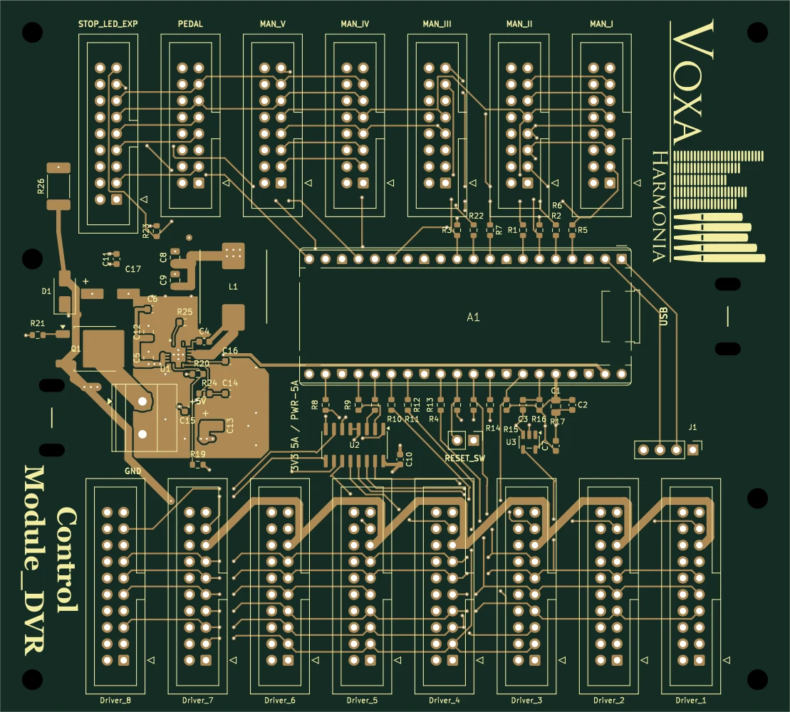
The central ModSystem controller built around a Raspberry Pi Pico. It connects manuals, a pedalboard and the stop module, with separate driver-bus connections.

Technical features
  • Five manual ports and one pedalboard port, with IDC 2×8 connectors.
  • Dedicated Stop / LED / Expression connection and eight IDC 2×10 driver ports.
  • USB connection; central power distribution and module selection.
View details at Voxa Harmonia
MOD / 02Control Module LED — PCB illustration

LED control

Control Module LED

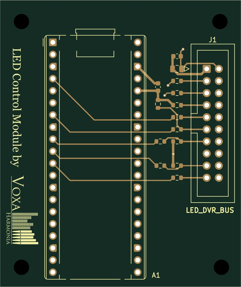
A dedicated USB-MIDI controller for daisy-chained LED Driver 64 boards. It converts computer MIDI messages into LED-driver control signals.

Please note LED power is supplied separately through the driver boards’ 5 V power connectors.

Technical features
  • Raspberry Pi Pico, powered by USB.
  • BUS_OUT → LED Driver 64 BUS_IN, using an IDC 2×10 connection.
  • Up to 3–4 LED Driver 64 modules can be daisy-chained: 3 modules provide 192 LED channels and 4 provide 256, with firmware configured for the module count.
View details at Voxa Harmonia
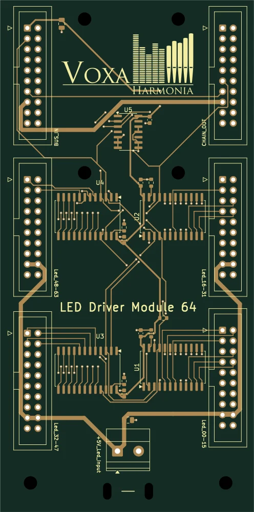
MOD / 03LED Driver 64 — PCB illustration

LED driving

LED Driver 64

A driver board for 64 individual LED channels, using four TLC5925 constant-current ICs. BUS_IN and CHAIN_OUT allow daisy-chaining to further boards.

Technical features
  • Four LED connectors, each with 16 channels.
  • 3.3 V control bus and a separate +5V_LED power input.
  • Sequential channel order: LED 00–63.
View details at Voxa Harmonia
MOD / 04Manual 64 Hall — PCB illustration

Keyboard – digital Hall

Manual 64 Hall

A manual board for 64 individual digital Hall sensors. Magnetic key sensing provides contactless on/off states to the central controller.

Please note External Hall switches are placed at the keys. This version senses on/off states.

Technical features
  • 64-pin signal header and six grouped power connectors.
  • Eight SN74HCS165 input ICs, with filtered and pulled-up inputs.
  • IDC 2×8 control bus; 3.3 V digital sensors.
View details at Voxa Harmonia
MOD / 05Manual 64 Reed — PCB illustration

Keyboard – switch matrix

Manual 64 Reed

A manual board that reads an 8×8 switch matrix for reed-switch or other suitable contact keyboards. The matrix accepts 64 switching points.

Technical features
  • Dedicated 8×8 Col-to-Row matrix connector.
  • Serial scanning based on 74HC595 and 74HC165.
  • IDC 2×8 connection to the central Control Module Driver.
View details at Voxa Harmonia
MOD / 06Manual 64 Velocity — PCB illustration

Keyboard – analogue Hall

Manual 64 Velocity

A board sampling 64 analogue Hall inputs to track key movement. Central-controller firmware can derive key velocity from the 12-bit ADC’s raw samples.

Please note Velocity operation requires calibration and suitable controller firmware. Firmware implementation and physical prototype measurements are still in development.

Technical features
  • Four 16:1 multiplexers, a TLV9064 buffer and an ADC128S102 ADC.
  • 64 separate sensor signals; external DRV5055 sensors.
  • IDC 2×8 bus; 3.3 V analogue sensor system.
View details at Voxa Harmonia
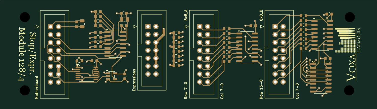
MOD / 07Stop Expression 128 — PCB illustration

Stops and expression

Stop Expression 128

A module for stop switches and four analogue expression controls. It forwards switch-matrix and pedal signals to the central controller.

Technical features
  • Col-to-Row matrix inputs for stop switches.
  • Four expression inputs with an MCP3204 12-bit ADC.
  • Serial control bus with individual module selection.
View details at Voxa Harmonia
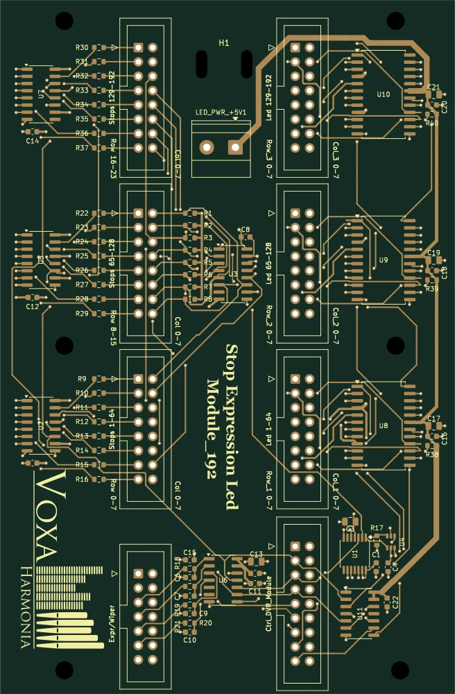
MOD / 08Stop LED Expression 192 — PCB illustration

Stops, LEDs and expression

Stop LED Expression 192

A board combining three 8×8 stop banks, LED feedback and four expression inputs. A single module handles switch scanning and illuminated stop indication.

Please note The 5 V LED supply and the 3.3 V logic bus use separate power networks.

Technical features
  • 192 switching points across three 8×8 banks.
  • Three MAX7219 LED-matrix drivers.
  • Four analogue expression inputs using an MCP3204 ADC.
View details at Voxa Harmonia
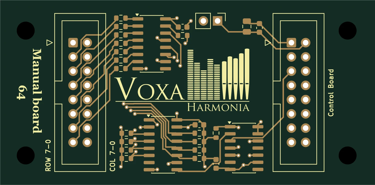
MOD / 098×8 Scan Matrix LED — PCB illustration

LED-matrix connections

8×8 Scan Matrix LED

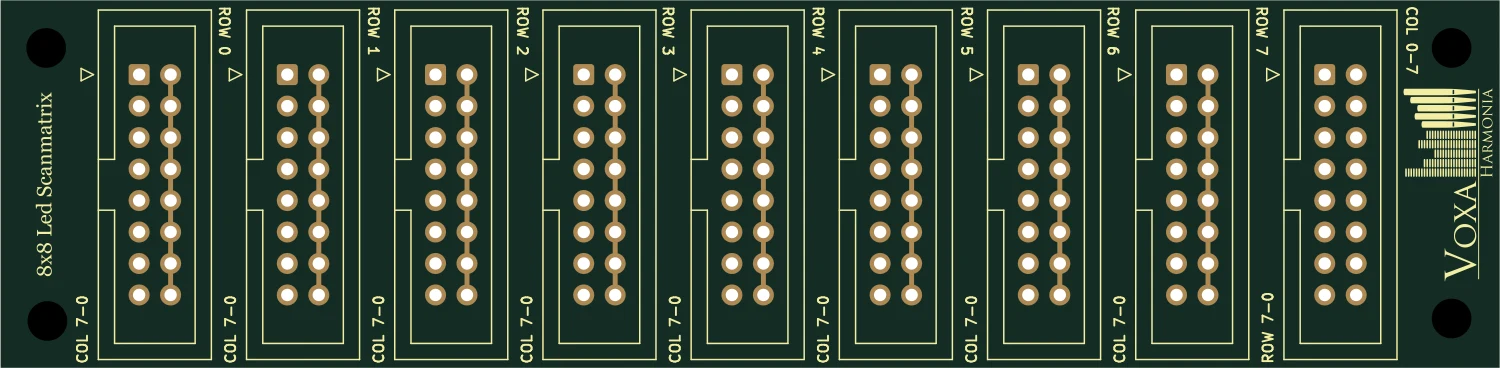
An 8×8 row–column connection board for an LED matrix. IDC connectors provide organised wiring for 64 matrix positions.

Technical features
  • Eight rows and eight columns.
  • IDC 2×8 connectors for the matrix and common bus.
  • For an external LED-matrix driver, such as the LED ports of Stop LED Expression 192.
View details at Voxa Harmonia
MOD / 108×8 Scan Matrix – diode — PCB illustration

Switch matrix

8×8 Scan Matrix – diode

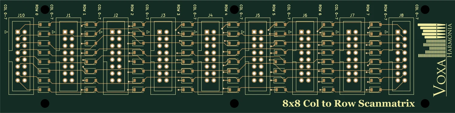
A Col-to-Row matrix board organising 64 switching points. Individual 1N4148W diodes provide isolation within the switch network.

Technical features
  • 8×8 switching points with 64 individual diodes.
  • IDC 2×8 connectors.
  • For Manual 64 Reed and suitable stop-matrix inputs.
View details at Voxa Harmonia

02 / Selection guide

Which module does my console need?

Start with what the console must do and how it is built. These four areas help you list the signals involved and identify relevant modules. Before settling on an assembly, review its connections, power requirements and firmware functions together.

01

Sensing manuals and pedalboard keys

For contactless on/off key sensing, consider the digital Hall inputs of Manual 64 Hall. Manual 64 Reed scans an 8×8 switch matrix for reed contacts or other suitable keyboard contacts. Manual 64 Velocity is intended to sample analogue Hall sensors and track key movement; velocity firmware implementation and physical prototype measurements remain in development. Treat this variant as a development option. Alongside the number of keys, record the sensor type, its position and the available wiring space.

02

Stop switches and expression pedals

Stop Expression 128 is a starting point when you need stop-switch inputs and analogue pedal inputs. If the same assembly also needs illuminated stop feedback, Stop LED Expression 192 combines three 8×8 stop banks with LED-matrix drivers. Both modules provide four analogue expression inputs. When choosing between them, describe the stop-bank layout, pedal electrical characteristics and intended indication as well as the number of switches. This helps establish the actual input and feedback requirements.

03

LED feedback for stops and controls

For a separate LED control path, Control Module LED converts USB-MIDI messages into control signals for LED Driver 64. Each driver handles 64 individual LED channels; up to 3–4 modules can be daisy-chained to build a 192–256-channel LED system, with firmware configured for the module count. The LEDs need a separate 5 V supply. For a row-and-column LED arrangement, the 8×8 Scan Matrix LED connection board may be relevant alongside a suitable external matrix driver. Individual LED channels and an LED matrix require different wiring arrangements.

04

Connecting the console as a system

Control Module Driver is the central connection point for manuals, the pedalboard and the stop module. It provides five manual ports, one pedalboard port and dedicated module connections. The diode version of 8×8 Scan Matrix organises 64 switch positions with individual isolation diodes and requires a suitable matrix input. For a complete console, map the signal paths and module connections first, then discuss the power supplies and desired MIDI mapping. Connector size alone does not establish electrical compatibility.

03 / MODSYSTEM

How the functions connect

Keys, stop switches and expression pedals reach the central controller through their corresponding input modules. LED feedback has a separate driver path. This is a functional overview; wiring and power distribution must be planned for the selected modules.

Console: manuals, stops, expression
Console: manuals, stops, expression ↗
USB-MIDI LED chain · separate 5 V supply
USB-MIDI LED chain · separate 5 V supply ↗

System overview diagrams. Confirm the exact wiring and power requirements for your selected modules before installation.

04 / Questions

Questions to ask before building an organ console

An organ console brings several types of signal together: the switching states of keys and stops, analogue pedal positions and visual feedback from the computer. Each calls for a different input or driver. ModSystem helps you choose electronics by function, whether you are planning a DIY MIDI organ or an electronic conversion of an existing console. The sensors, wiring and controller firmware need to be considered together. A clear description of those connections is more useful than choosing a board by its channel count alone.

I need electronics for a DIY MIDI organ. Where should I start?

List the number of keys in each manual and pedalboard, the sensor types, stop switches, expression pedals and LEDs. That establishes which input and driver functions you need. Prepare the intended MIDI mapping for your virtual organ software too, so the hardware and software requirements can be discussed together.

How do the Hall and reed manual boards differ?

Manual 64 Hall accepts on/off signals from individual digital Hall sensors. Manual 64 Reed reads switch positions arranged in an 8×8 matrix. Choose according to the sensors already fitted or planned for the keyboard. Their signal wiring and input arrangements differ, so they should not be treated as interchangeable connections.

Does Manual 64 Hall measure key velocity?

The digital Hall version senses on/off states. The analogue Hall-based Manual 64 Velocity is intended to sample key movement. Velocity operation needs suitable controller firmware and calibration; firmware implementation and physical prototype measurements are still in development. It should therefore not be specified as a finished velocity solution.

Can I use ModSystem with Hauptwerk or GrandOrgue?

Discuss the exact organ software and controller firmware versions during planning, along with MIDI message types, channel assignments and stop-feedback mapping. Those details are needed to assess the proposed configuration. This overview does not establish general compatibility or compatibility with every software version.

Can I select modules for an existing organ console?

Document the existing key sensors, switches and wiring first. The relevant connections can then be assessed against the module requirements. A description of the console, connector information and photographs will help. The relationship between mechanical components, sensors and electronics needs to be reviewed for the individual project.

Can one board read stop switches and operate their lights?

Stop LED Expression 192 combines stop-switch scanning, LED-matrix driving and four expression inputs. For a separate LED system, consider Control Module LED with LED Driver 64. Select the arrangement according to the physical layout and number of indicators, and agree how the software should return feedback.

How do I request a quotation for the modules?

Use the contact option on the Voxa Harmonia main website to describe your project and the modules you are considering. The required configuration, functions still in development and ordering terms can be clarified directly. The checklist below helps prepare an enquiry even if you do not yet have a complete circuit or wiring plan.

Which organ components are included in the ModSystem range?

The organ components presented here are electronic boards: central controllers, manual input boards for key sensors, stop and expression modules, LED drivers and matrix connection boards. Discuss the keyboard, sensors, mechanical parts and power supply separately when planning the build. Selecting a module does not by itself constitute an order for a complete, ready-to-install console.

05 / VOXA HARMONIA

Let’s discuss your organ console.

You do not need a finished circuit diagram to start an enquiry. A clear project description helps identify the components you already have and the functions that still need electronics. Contact Voxa Harmonia through the main website to discuss your requirements.

  • Number of manuals and pedalboards, key counts and sensor types
  • Number of stop switches, push buttons and required LED indicators
  • Number of expression pedals and their known electrical characteristics
  • Organ software, version and intended MIDI message mapping
  • A brief description of existing wiring, power supplies and mechanical layout

Quotations and order arrangements are handled on the Voxa Harmonia website.